SAS PCB
Where Quality Meets Innovation in PCB Assembly
PCB Design For Manufacturing (DFM) Tips
Tip 07:
Thermal Relief on THT Ground Apertures
What is meant by “thermal relief” on a PCB?
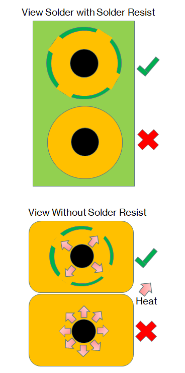
PCB Thermal relief refers to ensuring that the correct amount of heat is applied to a given pin when soldering either a through hole components legs or surface mount components with pins.
Thermal and thermal relief pads are used to achieve this. A Thermal relief pad is a small void around the through hole pin which acts to prevent heat conducting. This is because PCBs contain usually a ground layer of copper and a power layer also made from copper. As copper is also an excellent thermal conductor this can cause issues with soldering if the heat from the solder is dissipated too quickly.
Thermal pads (or sometimes paste depending on the application) do the opposite job of dissipating heat. Too much heat will damage components and/or the board itself. To avoid this; thermal pads improve heat dissipation. They are usually Aluminium or metal composite depending on the application.
While we are referring to Thermal Relief in regards to purely board assembly, it is also a very important consideration for board operation. Many modern SMT devices can emit heat especially in the case of Microprocessors. Any chassis or casing that a PCB may sit in will also affect heat dissipation.
What are the best thermal relief practices?
It's important to consider how difficult it may be to solder or rework components especially on multi-layer PCBs. Remember that thermal relief needs to be designed in to make solder easy to flow and not dissipate heat too quickly.
Multi-layer assemblies can even cause problems to more automated soldering processes like wave machines or selective soldering if not designed for manufacture. Don't just assume that an automated soldering process will solve all thermal related soldering difficulties.
As mentioned above it's usually component leads dissipating heat in to ground or power planes that commonly cause the most problems, this is because the heat is dissipated away from intended joint into ground or power planes.
However, SMT components can also be negatively affected by improperly thought-out thermal relief. An imbalance of temperature when soldering these components can result in a tombstone effect.
Amending the pad pattern on difficult pads can be all that's required to achieve 100% solder fill, adding 2, 3 or 4 thermal relief spokes can prevent heat from leeching away from a difficult THT solder aperture.
Remember that there are positives and negatives to each method of thermal relief so always check to make sure you are using the most appropriate one.
Sometimes it can not be helped due to a board's necessary functionality and/or electrical demands to include large areas of metal within the design. Designs with high current requirements will require enhanced power integrity and therefore larger areas of metal. As a result it can seem like the board designing is having to design with two opposing objectives when designing for manufacturing. However, this is the type of situation where thermal relief can therefore provide much-needed compromise.

Do You Like What You See?
Join the ranks of satisfied engineers and businesses. Register and quote today!
Register